LESGO

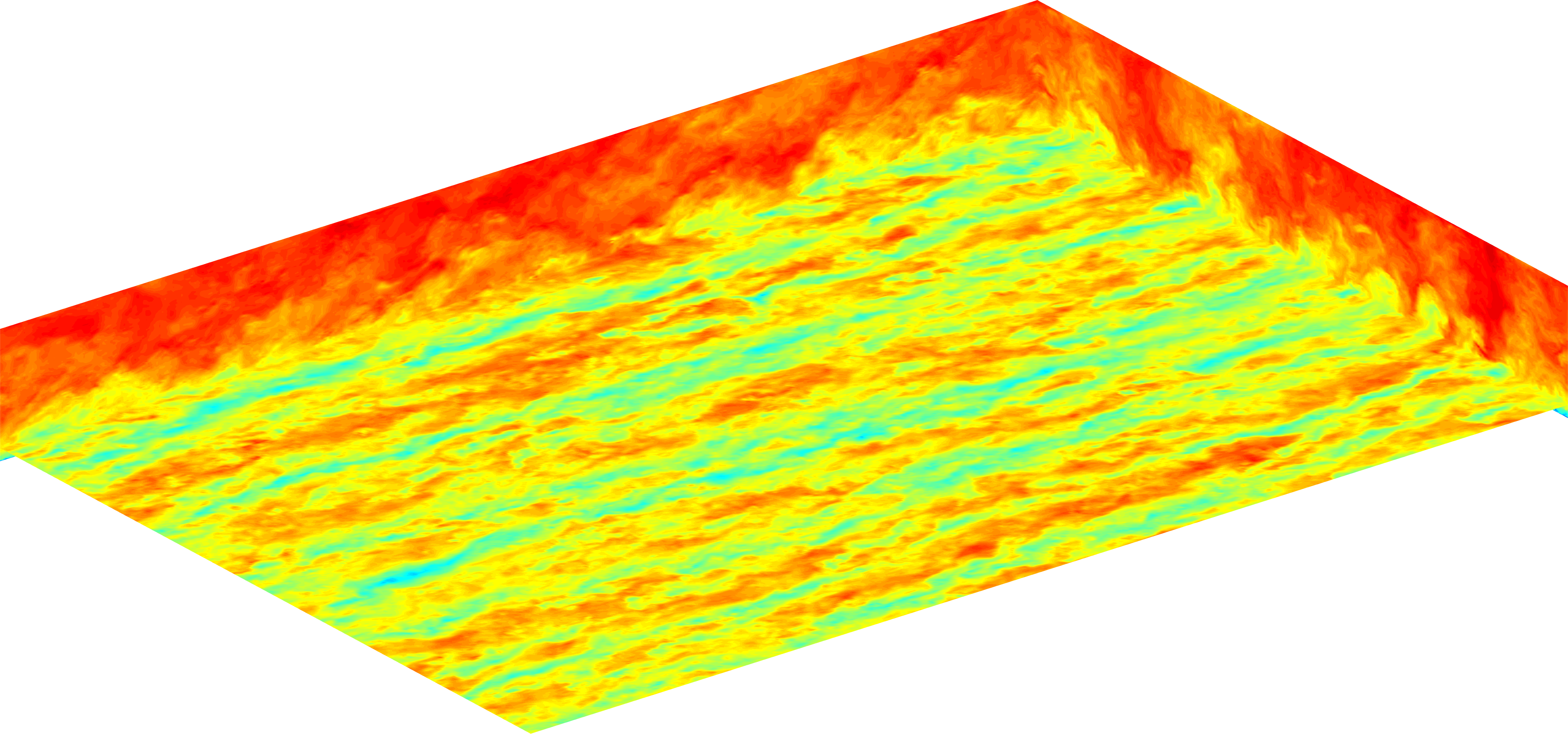
LESGO is a parallel pseudo-spectral large-eddy simulation code.
Actuator disk model
Each turbine is represented as a drag disk with a force that depends on the velocity at the disk (averaged in time and space). This force is distributed across several grid points that together represent the turbine. For large arrays the coarse grid resolution does not allow for the modeling of individual blades. LESGO’s implementation does not include rotation of the drag disk, and tangential forces are not applied to the flow.
A smoothed normalized indicator function \(\mathcal{R}(\mathbf{x})\) is used to distribute the turbine thrust force \[\mathbf{F}(\mathbf{x}) = -\frac{1}{2} \frac{\pi D^2}{4} \rho C_T’ \left \langle \bar{u}^T_d \right \rangle^2 \mathcal{R}(\mathbf{x}) \, \mathbf{\hat{e}_1} \] where \(\rho\) is the fluid density, \(C_T’\) is the local thrust coefficient, \(\left \langle \bar{u}^T_d \right \rangle\) is the disk and time-averaged velocity, \(D\) is the diameter of the disk, and \(\mathbf{\hat{e}_1}\) is the unit vector pointing outward from the disk in the direction of the flow. The disk averaged velocity is also found using the smoothed indicator function
\[ \left\langle u_d \right\rangle = \int \mathcal{R}(\mathbf{x}) \, \tilde{\mathbf{u}}(\mathbf{x}) \, d^3\mathbf{x}. \]
A correction factor can also be included to correct measured disk-averaged velocity when running simulations on coarse grids.
\[ \left\langle u_d \right\rangle = M \int \mathcal{R}(\mathbf{x}) \, \tilde{\mathbf{u}}(\mathbf{x}) \, d^3\mathbf{x}. \]
Settings
The first settings specify the wind-turbine array geometry and orientation. The user can set the number of turbines in each direction as well as their size. Several common orientations (aligned, staggered, etc) are available. The user is also able to specify the thrust coefficients \(C_T’\).
In addition to easy to use options for regularly arranged wind farms, the user may also specify the details for each wind turbine in the farm by writing a custom “input_turbines/param.dat” file. This allows for any wind farm configuration and allows each turbine to have its own rotor diameter, orientation, and thrust coefficient. The thrust coefficients and orientation of each turbine may also be changed in time by writing custom input files in the folder “input_turbines”.
Technical settings relating to the filtering of the indicator function, time averaging, and output writing are also available in “lesgo.conf”. More details are also provided as comment in the input file.
Output
All output files relating to the turbines can be found in the “turbine” folder. The following quantities are also written to file for each turbine in the files “turbine_#.dat”.
- current time (dimensional)
- disk center u velocity (dimensionless)
- disk center v velocity (dimensionless)
- disk center w velocity (dimensionless)
- instantaneous disk-averaged velocity (dimensionless)
- current time and disk-averaged velocity (dimensionless)
- counter clockwise angle, when viewed from above, from the -x direction \(\theta_1\) (degrees)
- angle above the horizontal \(\theta_2\) (degrees)
- local thrust coefficient \(C_T’\)
The values of the time and disk-averaged velocity for each turbine as well as the filtering time scale are written to file “u_d_T.dat”. The horizontally averaged streamwise velocity at the top of the domain is written to “vel_top.dat”
References
Calaf M, Meneveau C, and Meyers J. “Large eddy simulation study of fully developed wind-turbine array boundary layers.” Physics of Fluids 22 (2010). 015110.
Meyers J and Meneveau C. “Large eddy simulations of large wind-turbine arrays in the atmospheric boundary layer.” 50th AIAA Aerospace Sciences Meeting, (2010). Orlando, FL. AIAA Paper No. 2010-827.
Shapiro C, Gayme D, and Meneveau C. “Filtered actuator disks: Theory and application to wind turbine models in large eddy simulation. arXiv.org. (2019).